TM 5-3895-359-14&P
b. Place a few drops of cutting oil on the tool.
Then, using a socket and a speed handle,
remove the excess stock so that the lower end
of the injector tube is from flush to .005 " below
the finished surface of the cylinder head.
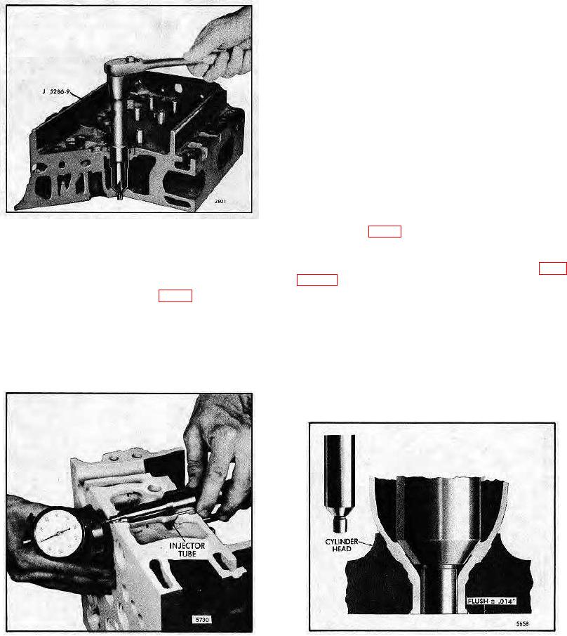
3. Ream the bevel seat in the injector tube:
The tapered lower end of the injector tube must provide
a smooth and true seat for the lower end of the injector
nut to effectively seal the cylinder pressures and
properly position the injector tip in the combustion
chamber. Therefore, to determine the amount of stock
that must be reamed from the bevel seat of the tube,
refer to Fig. 6.
Install gage J 25521 in the injector tube. Zero the sled
gage dial indicator J 22273 to the fire deck. Gage J
25521 should be flush to .014 " with the fire deck of the
Fig. 5 - Reaming Injector Tube for Injector Nut
cylinder head (Fig. 7).
NOTE: Any fire deck resurfacing work must be done
b. Turn the reamer in a clockwise direction
prior to final injector tube seat gaging. Refer to Page
(withdrawing the reamer frequently for removal
10-2-22 for resurfacing instructions.
of chips) until the lower shoulder of the reamer
contacts the injector tube (Fig. 4). Clean out all
With the first reaming operation completed and the
of the chips.
injector tube spot-faced, wash the interior of the injector
2. Remove excess stock:
tube with clean solvent and dry it with compressed air.
Then perform the second reaming operation as follows:
a. With the cylinder head bottom side up, insert
the pilot of cutting tool J 5286-8 into the small
a. Place a few drops of cutting oil on the bevel
hole of the injector tube.
seat of the tube. Carefully lower the reamer J
5286-9 into the injector tube until it contacts the
bevel seat.
Fig. 7 - Measuring Relationship of Gage to Fire Deck
Fig. 6 Measuring Relationship of Bevel Seat of
of Cylinder Head
Injector Tube to Fire Deck of Cylinder Head
10-3-27

