TM 5-3895-359-14&P
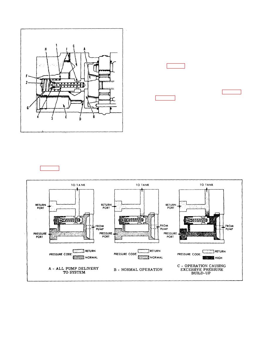
ported past the sliding spool (1) to the return circuit by
way of passage C.
2. When all pump delivery can pass through the
restriction to the load, the spool is held in the closed
position by the large spring (2) and passage C is
blocked from chamber B.
This is the condition
illustrated in Figure 4-A.
3. When pump delivery is greater than the flow
rate determined by tile restriction (D), a pressure build-
up in chamber B forces the spool open against the large
spring force. Excess fluid is throttled past the spool to
passage C and back to inlet, as shown in Figure 4-B.
4. Figure 4-C shows the condition when pressure
in thesystem builds up to the relief valve setting
Pressure is transmitted through sensing orifices G and H
aid forces the ball (4) from its seat. Fluid flow is then
from chamber B, through orifice D, passage E, orifices
G, H and J to, passage C and to inlet. The pressure
drop across restriction D resulting from this flow causes
a differential pressure on the spool ends and the spool is
FIGURE 3
shifted against the large spring, permitting the
remainder of pump delivery to flow from chamber B to
D. FLOW CONTROL AND RELIEF VALVE
passage C.
5. A second function of the valve sub-assembly
1. Maximum fluid delivery and maximum system
and #2 is to hold the pressure plate against the pump
pressure are determined by the integral flow control and
cartridge until pressure builds up in chamber B.
relief valve (Figure 3). The rate of flow depends on the
sizes of the restriction, (D) in the cover. Excess oil is
FIGURE 4
INSTALLATION AND OPERATION
1. Care must be exercised in pump mounting to
2. Pumps are manufactured for either right hand
insure correct alignment with the driving medium. If
or left hand rotation. They must be driven in the
indirect drive is used} belts and pulleys must be properly
direction of the arrow on the pump ring or severe
aligned and adjusted to prevent undue side loads being
damage may result.
imposed on the shaft bearings.
11-2


