TM 5-3895-359-14&P
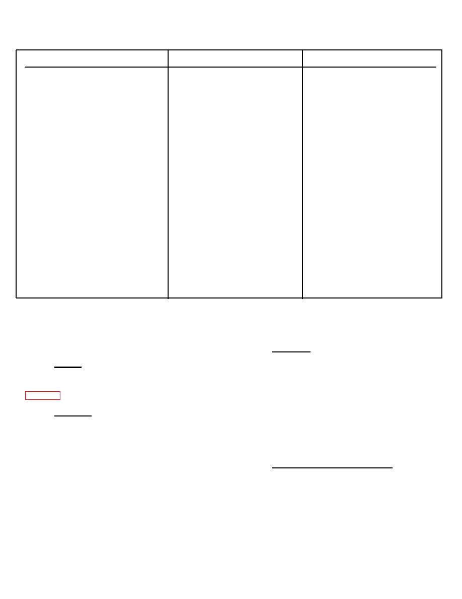
TABLE II. - TROUBLE SHOOTING CHART (CONTINUED)
TROUBLE
PROBABLE CAUSE
REMEDY
PUMP NOT DELIVERING OIL
Vane or vanes stick in rotor slots.
Disassemble pump. Examine rotor
(CONTINUED)
slots for dirt, grime or small metal
chips. Clean rotor and vanes in a
good grade solvent (mineral oil or
kerosene). Reassemble parts and
check for free vane movement.
Oil viscosity too heavy to pick up
Use fluid of the proper viscosity.
prime.
NOISY PUMP OPERATION
Pump intake partially blocked.
Drain system completely. Flush to
clear pump passages. Flush and
refill system with clean oil as per
prescribed recommendations.
Air vent for oil tank clogged or
Remove filler cap and clean -air
dirty strainer.
vent slot. Check strainer in tank
for clogged condition. Drain, flush
and add clean oil to system.
Air being drawn into pump return
Pump must receive air-free oil or
connection.
pump will be noisy. Drain system.
Tighten all hose connections. Clean
or replace filter. Add clean oil of
the proper viscosity.
Leaking shaft seal.
Check pump shaft seal and replace
if sealing lip has been damaged.
Check for scoring of shaft at seal
contact area. Replace faulty shaft.
OVERHAUL
c. Remove the pressure plate. Note the
position of the pump ring for reassembly. Pull out the
A. DISASSEMBLY
ring locating pins and remove the ring. Remove the
vanes from the rotor slots and slide the rotor off the
CAUTION: Before removing a unit to be serviced, be
driveshaft. Remove the body "O" ring.
sure it is not under pressure.
3. Shaft End - Remove the driveshaft key.
Remove the bearing retaining snapring and gently tap
the splined end of the shaft to remove the shaft and the
1. General - Use a puller to remove shaft gears or
outboard bearing. Support the outboard bearing inner
race in an arbor press and press out the shaft. Remove
During disassembly, pay special attention to
the seal from the body with a hooked tool. Remove the
identification of parts for proper reassembly. Refer to
inboard bearing from the shaft end of the body with a
bearing puller or by tapping it out from the cover end.
discussion.
2. Cover End - Clamp the pump mounting flange
B. INSPECTION, REPAIR AND REPLACEMENT
in a vise. Be certain to use protective jaws.
a. Reservoir Remove the tank cover screw,
Discard all used seals and gaskets. Wash all parts in a
lockwasher, washer, guide and guide gasket. Lift off the
clean mineral oil solvent and place them on a clean, lint-
tank cover and gasket and remove the tank screws,
free surface for inspection. Soak new seals and "O"
tank, gaskets and spacers.
rings in hydraulic fluid prior to reassembly.
b. Remove the cover screws and separate
1. Cartridge, Body and Pressure Plate - Inspect all
the cover from the pump. Remove the control valve
wearing surfaces for scoring. Light scoring can be
subassembly and spring and the cover "0" ring.
removed from the body and wear plate with crocus cloth
or by stoning or lapping.
NOTE: Control valve subassemblies are preset and
Inspect the vanes for wear. Vanes must not
tested by Vickers and should not be disassembled. If
have excessive play in the rotor slots or burred edges.
any part is defective, the complete subassembly should
Replace the vanes if they are defective. Check each
be replaced.
rotor slot for sticky vanes or for wear. Vanes should
drop in the rotor slots from their own weight when both
the rotor and vanes are dry.
11-5


