TM 5-3895-359-14&P
INJECTOR TIMING
If it is suspected that a fuel injector is "out of time", the
injector rack-to-gear timing may be checked without
disassembling the injector.
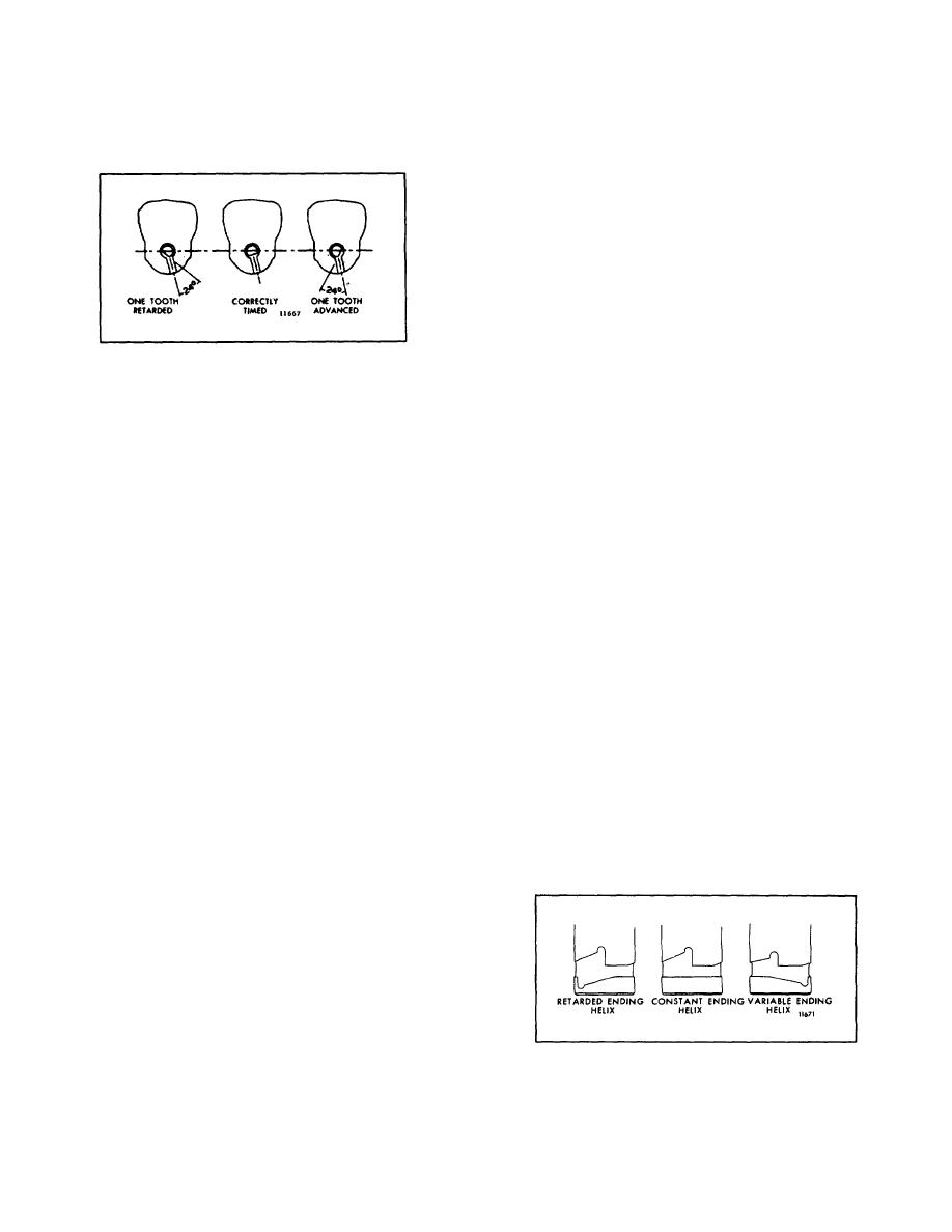
A hole located in the injector body, on the side opposite
the identification tag, may be used to visually determine
whether or not the injector rack and gear are correctly
timed. When the rack is all the way in (full-fuel
position), the flat side of the plunger will be visible in the
hole, indicating that the injector is "in time". If the flat
side of the plunger does not come into full view (Fig. 3)
Fig. 3 Injector Rack-to-Gear Timing
and appears in the "advanced" or "retarded" position,
disassemble the injector and correct the rack-to-gear
timing.
INJECTOR SPRAY TIPS
Due to a slight variation in the size of the small orifices
Flow gage J 25600 may be used to select a spray tip
in the end of each spray tip, the fuel output of an injector
that will increase or decrease fuel injector output for a
may be varied by replacing the spray tip.
particular injector after it has been rebuilt and tested on
the calibrator.
EFFECT OF PRE-IGNITION ON FUEL INJECTOR
Pre-ignition is due to ignition of fuel or lubricating oil in
Before replacing the injectors, check the engine for the
the combustion chamber before the normal injection
cause of pre-ignition to avoid recurrence of the problem.
period. The piston compresses the burning mixture to
Check for oil pull-over from the oil bath air cleaner,
excessive temperatures and pressures and may
damaged blower housing gasket, defective blower oil
eventually cause burning of the injector spray tip and
seals, high crankcase pressure, plugged air box drains,
lead to failure of the injectors in other cylinders.
ineffective oil control rings or dilution of the lubricating
oil.
When pre-ignition occurs, remove all of the injectors
and check for burned spray tips or enlarged spray tip
orifices.
INJECTOR PLUNGERS
The fuel output and the operating characteristics of an
the hardened case and result in chipping at the helices
and seizure or scoring of the plunger.
injector are, to a great extent, determined by the type of
plunger used. Three types of plungers are illustrated in
Fig. 4. The beginning of the injection period is
controlled by the upper helix angle. The lower helix
angle retards or advances the end of the injection
period. Therefore, it is imperative that the correct
plunger is installed whenever an injector is overhauled.
If injectors with different type plungers (and spray tips)
are mixed in an engine, erratic operation will result and
may cause serious damage to the engine or to the
equipment which it powers.
Injector plungers cannot be reworked to change the
Fig. 4 Types of Injector Plungers
output or operating characteristics. Grinding will destroy
10-3-54


