TM 5-3895-359-14&P
FUEL INJECTOR CONTROL TUBE
1. Remove the bracket from the injector control tube.
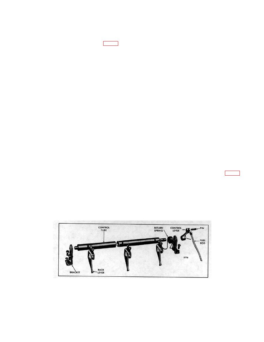
The fuel injector control tube assembly (Fig. 1) is
mounted on the cylinder head and consists of a control
2. Loosen the adjusting screws at each injector rack
tube, injector rack control levers, a return spring and
control lever.
injector control tube lever mounted in two bracket and
bearing assemblies attached to the cylinder head.
3. Disconnect the return spring from the bracket and
front or rear rack lever.
The injector rack control levers connect with the fuel
injector control racks and are held in position on the
4. Then remove the return spring and rack levers from
control tube with two adjusting screws. The return
the control tube.
spring enables the rack levers to return to the no-fuel
position. The injector control tube lever is pinned to the
end of the control tube and connects with the fuel rod
Inspection
which connects with the engine governor. Refer to
Chapter 10 for positioning of the injector rack control
Wash all of the injector control tube parts in clean fuel
levers.
oil and dry them with compressed air.
Remove Injector Control Tube
Examine the control tube, control lever, control tube
rack control levers and brackets for excessive wear,
cracks or damage and replace them if necessary. The
1. Remove the cotter pin and clevis pin connecting the
bearing in the bracket is not serviced separately.
fuel rod to the injector tube control lever.
Examine the return spring and replace it if worn or
fractured.
2. Remove the two attaching bolts and lock washers at
each bracket. Disengage the rack levers from the
injector control racks and lift the control tube
Assemble Injector Control Tube
assembly from the cylinder head.
With all of the parts cleaned and inspected and the
Disassemble Injector Control Tube
necessary new parts on hand, refer to Fig. 1 and
assemble as follows:
The injector control tube, one mounting bracket, a
1. Install the rack control levers on the control tube, with
spacer and injector control tube lever are available as a
the levers facing the front bracket position. Turn the
service assembly. When any part of this assembly
adjusting screws into the slots in the control tube far
needs replacing, it is recommended the complete
enough
to
position
the
levers.
service assembly be replaced.
Therefore, the
disassembly and assembly procedure for these items is
not included in the following:
Fig. 1. Injector Control Tube Assembly (Non-Spring Loaded)
10-3-50


