
TM 5-3895-359-14&P
Fig. 6 - Removing Oil Seals
7. If the oil seals need replacing, remove them with oil
the end of the tool with a hammer to remove the outer
and inner seals.
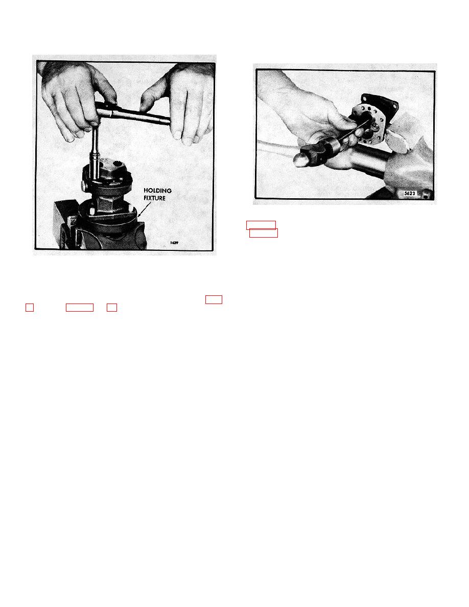
Fig. 5 - Removing Pump Cover
NOTE: Observe the position of the oil seal lips before
removing the old seals to permit installation of the new
Disassemble Fuel Pump
seals in the same position.
With the fuel pump removed from the engine and
Inspection
mounted in holding fixture J 1508-10 as shown in Fig.
Clean all of the parts in clean fuel oil and dry them with
follows:
compressed air.
1. Remove the eight cover bolts and withdraw the pump
Oil seals, once removed from the pump body, must be
cover from the pump body. Use care not to damage the
discarded and replaced with new seals.
finished faces of the pump body and cover.
Check the pump gear teeth for scoring, chipping or
2. Withdraw the drive shaft, drive gear and gear
wear. Check the ball slot in the drive gear for wear. If
retaining ball as an assembly from the pump body.
necessary, replace the gear.
3. Press the drive shaft just far enough to remove the
Inspect the drive and driven shafts for scoring or wear.
steel locking ball. Then invert the shaft and gear
Replace the shafts if necessary. The driven shaft is
assembly and press the shaft from the gear. Do not
serviced as a gear and shaft assembly only.
misplace the steel ball. Do not press the squared end of
the shaft through the gear as slight score marks will
The mating faces of the pump body and cover must be
damage the oil seal contact surface.
flat and smooth and fit tightly together. Any scratches or
slight damage may result in pressure leaks. Also check
4. Remove the driven shaft and gear as an assembly
for wear at areas contacted by the gears and shafts.
from the pump body. Do not remove the gear from the
Replace the pump cover or body if necessary.
shaft. The driven gear and shaft are serviced only as an
assembly.
The relief valve must be free from score marks and
burrs and fit its seat in the pump body. If the valve is
5. Remove the relief valve plug and copper gasket.
scored and cannot be cleaned up with fine emery cloth
or crocus cloth, it must be replaced.
6. Remove the valve spring, pin and relief valve from
the valve cavity in the pump body.
Current standard fuel pumps (with 1/4" wide gears)
incorporate a 1/8" shorter pump body with three drain
holes, a 1/8" shorter drive shaft and a cover with a 3/8"
inlet opening.
10-3-32
