TM 5-3895-359-14&P
EXHAUST VALVES
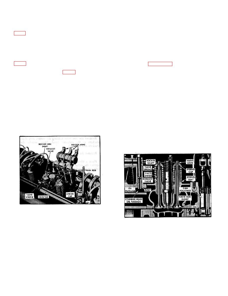
Two exhaust valves are provided for each cylinder.
Exhaust Valve Maintenance
to the proper seat angle and diameter. The valve stems
are ground to size and hardened at the end which
Efficient combustion in the engine requires that the
contacts the rocker arm.
exhaust valves he maintained in good operating
condition. Valve seats must be true and unpitted to
assure leakproof seating, valve stems must work freely
valve guides which are pressed into the cylinder head
and smoothly within the valve guides and the correct
valve clearance (Page 10-10-2) must be maintained.
Exhaust valve seat inserts (Fig. 2), pressed into the
Proper maintenance and operation of the engine is
cylinder head, permit accurate seating of the exhaust
important to long valve life.
Engine operating
valves under varying conditions of temperature and
temperatures should be maintained between 160-185F
materially prolong the life of the cylinder head. The
(71-85C). Low operating temperatures (usually due to
exhaust valves are ground to a 30 seating angle while
extended periods of idling or light engine loads) result in
the exhaust valve seat inserts are ground to a 31
incomplete combustion, formation of excessive carbon
seating angle.
deposits and fuel lacquers on valves and related parts.
and a greater tendency for lubricating oil to sludge.
The exhaust valve springs are held in place by the valve
spring caps and tapered two-piece valve locks.
Unsuitable fuels may also cause formation of deposits
on the valves, especially when operating at low
Excess oil from the rocker arms lubricates the exhaust
temperatures.
valve stems. The valves are cooled by the flow of air
from the blower past the valves each time the air inlet
When carbon deposits, due to partially burned fuel, build
ports are uncovered.
up around the valve stems and extend to that portion of
the stem which operates in the valve guide, sticking
valves will result. Thus, the valves cannot seat properly
and pitted and burned valves and valve seats and loss
of compression will result.
Fig. 1. Location of Exhaust Valves (Two-Valve
Cylinder Head)
Fig. 2. Assembly of Exhaust Valves and Guides
10-2-37


