TM 5-3895-359-14&P
g. Remove cotter pin and drive gear from shaft.
h. Remove key from shaft. Remove snap ring
adjacent to gear.
i. Remove driven gear and shaft. Remove
flange and adapter from vise or fixture and by
pressing on drive gear end of shaft, press out the
bearing. Be sure to coat drive shaft with white
lead, on area where pumps drive gear was
removed, to aid in sliding through the outboard
bearing.
j. Remove seal assembly and locating snap ring
FIGURE 4 Marking of the Gears for Location
and washer from pump drive shaft.
k. Remove dowel pins from cover and adapter
castings, with a pliers or a lever jaw wrench.
NOTE:
Replace roller bearings only if
necessary and then only with the
same make and type as originally
installed.
l. Check bearings for freeness of rollers, pitted,
broken or excessively worn rollers.
Replace
FIGURE 5 Tool Dimensions
bearing, if it is possible to insert a
feeler of 0.020" between rollers. More gap indicates
rollers are worn excessively.
m.
Remove roller bearings by starting them with
tool shown in Figure 5. Insert tool under the
bearing and into the cored hole, behind bearing
bores, Figure 6.
n.
Complete removal of the bearing, using tool
bar.
o.
Remove outboard bearing retaining snap ring
with ring pliers.
p.
Reach down through the drive shaft bearing
bore with a brass drift punch and tap out the
outboard bearing. Tap opposite side alternately.
FIGURE 2
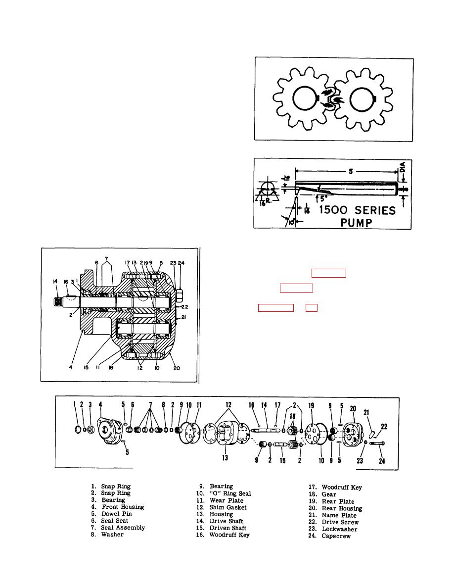
FIGURE 3 Exploded View of Hydraulic Pump
7-2


