
TM 5-3895-369-14
5-22. PISTON AND CONNECTING ROD REPLACEMENT/REPAIR (CONT).
Compressed air used for cleaning purposes must not exceed 30 psi (207 kPa). Use only with effective
chip guarding and personal protective equipment (goggles/shield, gloves, etc).
(3) Dry all parts using compressed air or lint-free cloth.
(4) Check piston and connecting rod for excessive wear and other damage. Replace parts failing inspection.
(5) Check remaining parts for wear and other damage. Replace parts failing inspection.
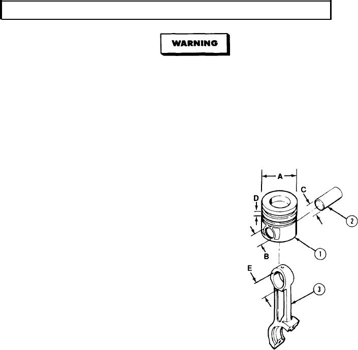
(6) Measure each piston (1) at position A.
Normal measurement is 4.0088 to 4.0117 in.
(101.823 - 101.896 mm). If above or below
limits, replace piston.
(7) Measure each piston (1) at position B.
Normal measurement is 1.5750 to 1.5758 in.
(40.006 - 40.025 mm). If above or below
limits, replace piston.
(8) Measure each wrist pin (2) at position C.
Normal measurement is 1.5744 to 1.5749 in.
(39.990 - 40.0032 mm). If above or below
limits, replace piston pin.
(9) Install each ring on piston (1) and measure
ring clearance (position D). If above or
below limits, replace ring. Normal
measurements are as follows:
(a) Top ring is 0.003 to 0.0059 in.
(0.076 - 0.150 mm).
(b) Intermediate ring is 0.003 to 0.0059 in.
(0.076 - 0.150 mm).
(c) Oil control ring is 0.0016 to 0.0051 in. (0.040 - 0.130 mm).
(10) Measure each connecting rod (3) at position E. Normal measurement is 1.5769 to 1.5784 in.
(40.053 - 40.092 mm). If above or below limits, replace connecting rod.
5-164