
TM 5-3895-369-14
4-139. VALVE BANK ASSEMBLY LEVERS AND LINKAGE REPLACEMENT.
This task covers:
b. Installation
a. Removal
INITIAL SETUP
Equipment Condition
Tools
Condition Description
TM or Para
Tool kit, general mechanic's: automotive
Dash panel removed.
Materials/Parts
Pins, cotter (9)
Removal.
a.
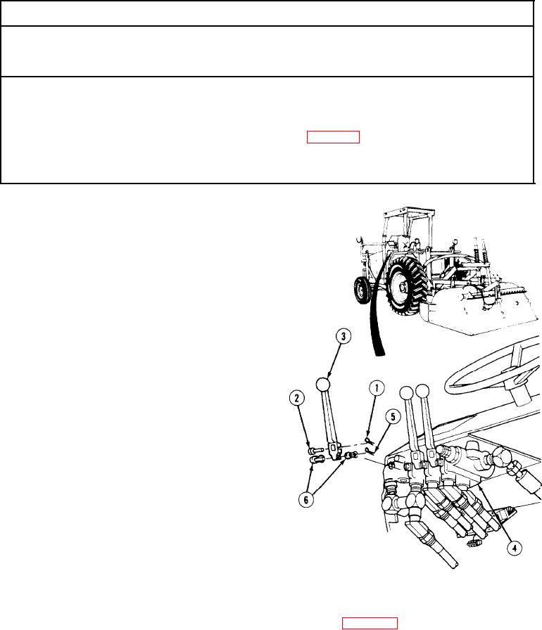
(1) Remove three cotter pins (1) and pins (2)
from valve handles (3) on control valve (4).
Discard cotter pins.
(2) Remove six cotter pins (5), three handle
links (6), and valve handles (3) from control
valve (4). Discard cotter pins.
Installation.
b.
(1) Install three valve handles (3) on control
valve (4) with three handle links (6) and six
cotter pins (5).
(2) Install three pins (2) through valve
handles (3) with cotter pins (1).
NOTE
Follow-on Maintenance: Install dash panel (para 4-128).
END OF TASK
4-454