
TM 5-3895-359-14&P
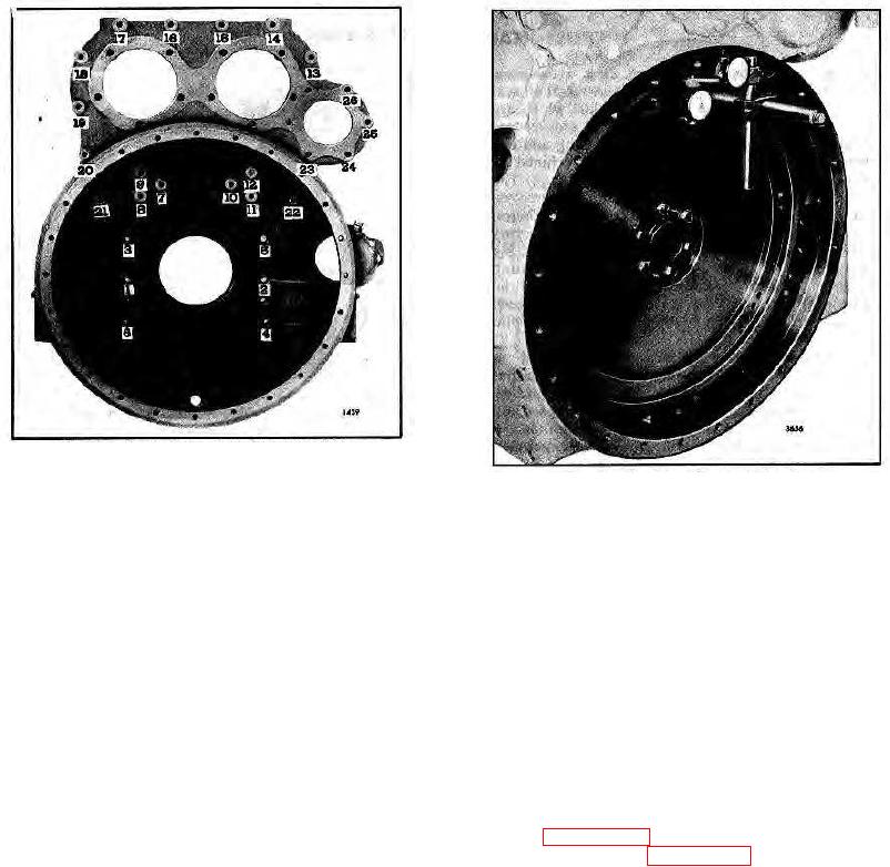
Fig. 4. Flywheel Housing Bolt Tightening
Sequence (Operation 2)
Fig. 5. Checking Flywheel Housing Concentricity
b. Position the dial indicators straight and square
e. If the runout exceeds the maximum limits,
with the flywheel housing bell face and inside
remove the flywheel housing and check for dirt
bore of the bell. Make sure each indicator has
or foreign material, such as old gasket material,
adequate travel in each direction.
between the end plate, flywheel housing and the
new gasket (and between the end plate and the
NOTE
cylinder block).
If the flywheel extends beyond the
f. Re-install the flywheel housing and the flywheel
housing bell, the bore and face must
and tighten the attaching bolts in the proper
be checked separately.
Use the
sequence and to the specified torque. Then
special adapter in the tool set to
recheck the runout. If necessary, replace the
check the housing bore.
flywheel housing.
13. Remove the bolts holding the lifter bracket to the
c. Pry the crankshaft toward one end of the block
flywheel housing. Affix a new gasket to the bracket,
to ensure the end play is in one direction only.
then alternately tighten the bracket-to-flywheel housing
and bracket-to-cylinder head bolts, thus drawing the
d. Adjust each dial indicator to read zero at the
bracket into the corner formed by the cylinder head and
twelve o'clock position.
Then rotate the
housing (Page 10-2-45).
crankshaft one full revolution, taking readings at
14. Install the oil pan (Page 10-5-21).
45 intervals (8 readings each for the bore and
15. Remove the engine from the overhaul stand and
the bolting flange face). Stop and remove the
complete assembly of the engine.
wrench or cranking bar before recording each
reading to ensure accuracy. The maximum
total indicator reading must not exceed .013 "
for either the bore or the face.
10-2-77