
TM 5-3895-359-14&P
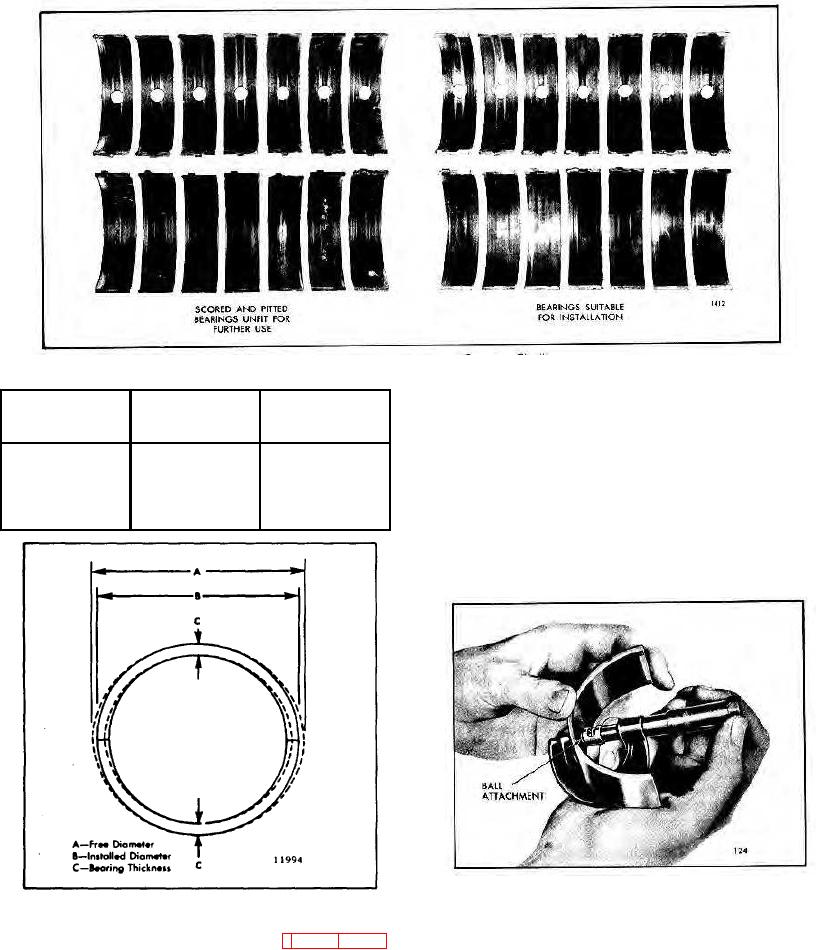
Fig. 5. Comparison of Main Bearing Shells Minimum
bearing shell thickness will be the total thickness of the
Minimum
steel ball in the tool and the bearing shell, less the
Bearing
Bearing
Worn
diameter of the ball. This is the only practical method
Size
Thickness
Thickness
for measuring the bearing thickness, unless a special
Standard
.1548"/.1533"
.1530"
micrometer is available for this purpose. The minimum
.002" Undersize
.1558"/. 1563'
.1540"
thickness of a worn standard main bearing shell is .1530
.010" Undersize
.1598"/.1603"
.1580"
" and, if any of the bearing shells are thinner than this
.020" Undersize
.1648"/.1653"
.1630"
dimension, replace all of the bearing shells. A new
.030" Undersize
.1698"/. 1703"
.1680"
standard bearing shell has a thickness of .1548 " to
.1553 ". Refer to Table 1.
In addition to the thickness measurement, check the
clearance between the main bearings and the
Fig. 7. Measuring Thickness of Bearing Shell
Fig. 6. Main Bearing Measurements
Measure the thickness of the bearing shells at point "C",
90 from the parting line, as shown in Figs. 6 and 7.
Tool J 4757, placed between the bearing shell and a
micrometer, will give an accurate measurement. The
10-2-61