TM 5-3895-359-14&P
two valve cylinder head (Fig. 10). Install the 1/2"
diameter nozzles at the ends of the cylinder head with
their openings toward the center of the engine. Press
the nozzles flush to .0312" recessed below the surface
of the cylinder head.
d.
Check to make sure the nozzles fit tight.
If necessary. use a wood plug or other suitable tool to
expand the nozzles, or tin the outside diameter with
solder to provide a tight fit. If solder is used, make sure
the orifices in the nozzles are not closed with solder.
7. Replace broken or damaged studs. Apply sealant to
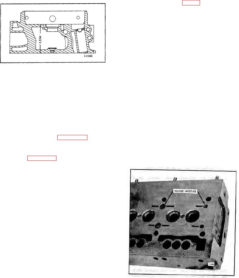
Fig. 9- Minimum Distance Between Top and Bottom
the threads of new studs and drive them to 10-25 lb-ft
Faces of Cylinder Head
(14-34 Nm) torque (water manifold cover studs) or to 25-
NOTE: When a cylinder head has been
refaced, critical dimensions such as the
8. Inspect all other components removed from the
protrusion of valve seat inserts, exhaust
cylinder head.
valves, injector tubes and injector spray
tips must be checked and corrected.
If a service replacement cylinder head is to be installed,
The push rods must also be adjusted to
it must be thoroughly cleaned of all rust preventive
prevent the exhaust valves from striking
compound, particularly inside the integral fuel manifolds,
the pistons after the cylinder head is
before installing the plugs.
A simple method of
reinstalled in the engine.
removing the rust preventive compound is to immerse
the head in a mineral spirits based solvent or fuel oil,
3. Install new injector tubes (Page 10-3-25) if the old
then scrub the head and go through all of the openings
tubes leaked or the cylinder head was refaced.
with a soft bristle brush. A suitable brush for cleaning
the various passages in the head can be made by
4. Inspect the exhaust valve seat inserts and valve
attaching a 1/8" diameter brass rod to brush J 8152.
guides (refer to Page 10-2-40).
After cleaning, dry the cylinder head with compressed
air.
5. Inspect the cam follower bores in the cylinder head
for scoring or wear. Light score marks may be cleaned
up with crocus cloth wet with fuel oil. Measure the bore
diameters with a telescope gage and micrometer and
record the readings. Measure the diameter of the cam
followers with a micrometer. Record and compare the
readings of the followers and bores to determine the
cam followers-to-bore clearances. The clearance must
not exceed .006" with used parts (refer to Page 10-2-
136 for specifications). If the bores are excessively
scored or worn, replace the cylinder head.
6. Check the water hole nozzles to be sure they are not
loose. If necessary, replace the nozzles as follows:
a. Remove the old nozzles.
b. Make sure the water inlet ports in the cylinder
head are clean and free of scale. The water
holes at each end of the head may be cleaned
up with a 1/2" drill and the intermediate holes
Fig. 10. Correct Installation of Water Nozzles in
may be cleaned up with a 13/16" drill. Break the
edges of the holes slightly.
Two-Valve Cylinder Head
c.
Press the nozzles in place with the nozzle
openings parallel to the longitudinal center line of the
10-2-24

