TM 5-3895-359-14&P
ENGINE SMOKES AND RUNS RICH
CLEANING Wash all parts in a mild solvent or fuel.
Blow air through orifices (holes) and channels in throttle
Dirty air filter: Clean per instructions.
body and fuel bowl. Do not probe with any sharp tools
Improper adjustment: Set Idle Needle 1 1/8 turns
which might damage small metering holes.
open from seat. Refer to Adjustment Instruction, page
REASSEMBLY Replace all worn or damaged parts use
14-15.
all new gaskets.
Bowl to body gasket leaks:
Tighten securely, or
Note; Body Gasket (18) is put on before float is
replace.
assembled, and round opening in gasket fits into groove
Air vent in carburetor plugged: Remove fuel bowl
of Venturi (11).
and idle needle. Clean air and idle channels thoroughly
Be sure that Notch in Venturi is facing toward float
with compressed air.
needle valve this is clearance for Main nozzle in throttle
ENGINE RUNS LEAN Improper adjustment: Set Idle
body.
Needle 1 1/8 turns open from seat.
Refer to
Assemble Throttle Valve (8) and Choke Valve (25) with
Adjustment Instructions, page 14-15.
part numbers facing to the outside, when valves are in
Idle holes plugged. Dirt in fuel delivery channels:
the closed position.
Remove fuel bowl and idle needle. Clean thoroughly
IMPORTANT: Be careful in tightening brass screws and
with compressed air.
fittings, so as not to strip threads and screw driver slots.
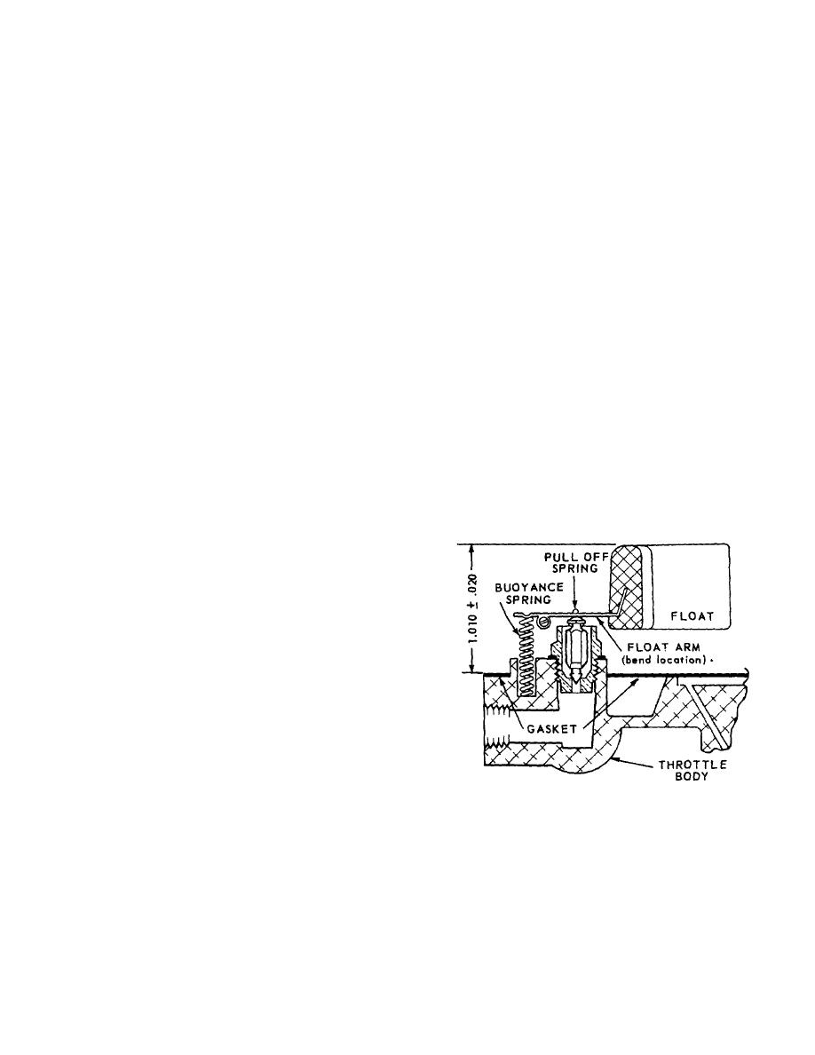
Low fuel level: See Fig.
30 and Float Setting
Tighten firmly but not excessively.
Instructions, page 14-15.
Valve Seat (16) 40 to 50 inch pounds torque Main Jet
Fuel filter plugged: Remove and clean.
(22) 50 to 60 inch pounds torque FLOAT SETTING,
ENGINE STARTS HARD Improper adjustment: Set
Fig. 30 With fuel bowl removed and float assembly in
Idle Needle 1 1/8 turns open from seat. Refer to
place, turn throttle body upside down so that float
Adjustment Instructions, page 14-15.
assembly is on top.
No fuel in carburetor: Check carburetor drain plug.
Check float height with a depth gauge. Setting should
Clean tank, filter and carburetor. Check fuel lines for
be 1.010 inch .020 above bowl gasket. If necessary,
obstructions, and test fuel pump.
bend float arm (at float), to obtain correct height.
Choke valve not closing:
Check linkage for proper
travel.
GOVERNOR SURGE Governor sticking:
Check
linkage for binding.
Throttle shaft and valve binding:
Remove and
replace.
shaft if worn. Clean carburetor body and reassemble
throttle shaft.
DISASSEMBLY Before disassembling: Clean outside
of carburetor from all foreign material.
IMPORTANT: When cleaning a completely assembled
carburetor do not blow with compressed air, you may
collapse the float.
For a complete disassembly, follow the sequence of part
reference numbers in the carburetor exploded view, Fig.
FIGURE 30. FLOAT SETTING
31. Nozzle Ref. 9, Fig. 29 is not removable.
IMPORTANT: Before removing Throttle and Choke
ADJUSTMENTS, Fig. 29 Turn Idle speed screw (5),
levers, note their position and location.
Optional
Fig. 31, in until throttle valve is slightly open. With
mounting is available and may differ from exploded
engine warmed up and running, turn adjusting screw in
view illustration.
or out as required to obtain desired low idle speed (1000
to 1200 r.p.m.).
14-15


