
TM 5-3895-359-14&P
Fig.
23, for clearance between
bearing and crank pin.
FIGURE 16
70166C
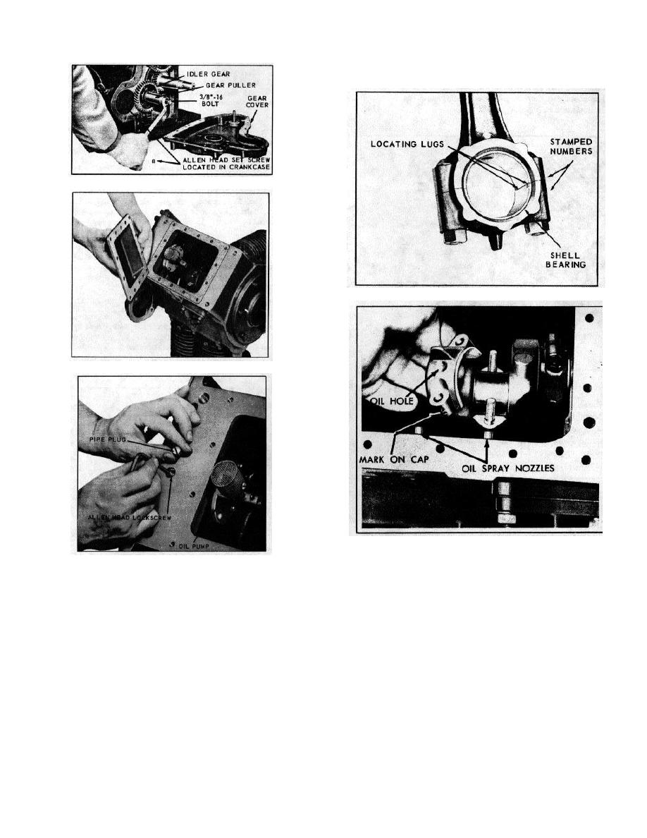
FIGURE 19 316307C
FIGURE 17
104721C
FIGURE 20
104819C
FIGURE 18
180178C
The piston skirt is cam-ground to an elliptical contour.
crankshaft until piston is at top, then push connecting
Clearance between the piston and cylinder must be
rod and piston assembly upward and out thru top of
measured at the center of the thrust face at the bottom
cylinder. Be careful not to mar the crank pin by allowing
of the piston skirt. Refer to Chart, Fig. 23, for proper
the rod bolts to strike or scrape across it. Place caps on
clearance. The thrust faces on the piston skirt are 900
rods immediately so that they will not be mismatched in
from the axis of the piston pin hole, with the wide
reassembly.
section of the piston skirt toward the maximum thrust
side, or opposite the crankshaft rotation.
NOTE
In reassembly; be sure piston and connecting rod
Care should be taken in reassembly
assemblies are put back into the same bore from which
to mount bearings properly. The cap
they were removed. Use a suitable ring compressor
should be assembled to the rod so
that the locating lug of both bearing
halves are on the same side as
illustrated in Fig. 19. Refer to chart,
14-10
