
TM 5-3895-359-14&P
High speed spring plunger on the seat in the governor
control housing.
CAUTION:
Overtightening of the
injector rack control lever adjusting
Injector fuel control racks in the full fuel position.
screws
during
installation
or
adjustment can result in damage to
Adjust the No. 1 injector rack control lever Fig. 2 first, to
the injector control tube.
The
establish a guide for adjusting the remaining injector
recommended
of
the
rack control levers.
adjusting screws is 24-36 lb-in(3-4
Nm).
1. Disconnect any linkage attached to the stop lever.
IMPORTANT: The above step should
2. Loosen the lock nut (Fig. 3) and back out the buffer
result in placing the governor linkage
screw approximately 5/8".
and control tube assembly in the
same position that they will attain
3. Loosen all the inner and outer adjusting screws (Fig.
while the engine is running at full
2). Be sure all the injector rack control levers are free
load.
on the injector control tubes.
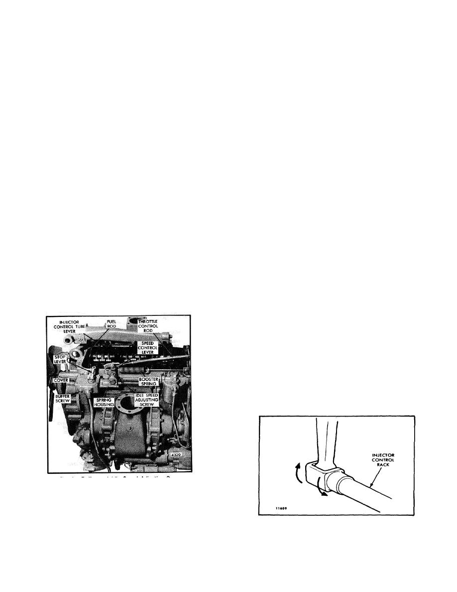
6. To be sure the control lever is properly adjusted, hold
4. Move the speed control lever to the maximum speed
the speed control lever in the maximum speed position
position.
and press down on the injector rack with a screw driver
or finger tip and note "rotating" movement of the injector
5. Move the stop lever to the run position. Hold it in
control rack (Fig. 4) when the speed control lever is in
that position with light finger pressure. Turn the inner
the maximum speed position. Hold the speed control
adjusting screw of the No. 1 injector rack control lever
lever in the maximum speed position and, using a screw
down until a step up in effort is noted. This will place
driver, press downward on the injector control rack. The
the No. I injector rack in the full fuel position. Turn
rack should tilt downward (Fig. 5) and when the pressure
down the outer adjusting screw until it bottoms lightly on
of the screw driver is released, the control rack should
the injector control tube. Then alternately tighten both
"spring" back upward.
the inner and outer adjusting screws.
If the rack does not return to its original position, it is too
loose. To correct, back off the outer adjusting screw
slightly and tighten the inner adjusting screw slightly.
The setting is too tight if when moving the stop lever
from the stop to the RUN position, the injector rack
becomes tight before the stop lever reaches the end of
its travel as determined by the stop under the governor
cover. This will result in a step up in effort required to
move the stop lever to the end of its travel. To correct
this condition, hack off the inner adjusting screw slightly
and tighten the outer adjusting screw slightly.
Fig. 3 - Buffer and Idle Speed Adjusting Screw
Fig. 4 -Checking Rotating Movement of
Injector Control Rack
10-10-5
