TM 5-3895-359-14&P
Flywheel Ring Gears
The starting motor drive pinion and the engine flywheel
ring gear must be matched to provide positive
engagement and to avoid clashing of the gear teeth.
Flywheel ring gears with no chamfer are used with
starting motors equipped with an overrunning clutch
drive.
Remove Starting Motor
Failure of the starting motor to crank the engine at
normal cranking speed may be due to a defective
battery, worn battery cables, poor connections in the
cranking circuit, defective engine starting switch, low
temperature, condition of the engine or a defective
starting motor.
If the engine, battery and cranking circuit are in good
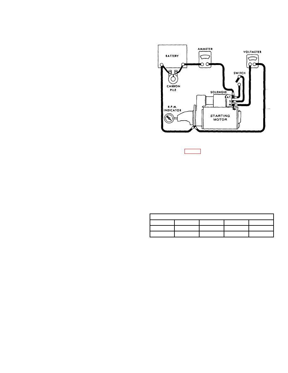
Fig. 3 - No-Load Test Circuit.
condition, remove the starting motor as follows:
No-Load Test (Fig. 3)
1. Remove the ground strap or cable from the battery or
the cable from the starting motor solenoid. Tape the
Connect a voltmeter from the motor terminal to the
end of the cable to prevent discharging the battery from
motor frame, and use an r.p.m. indicator to measure
a direct short.
armature speed. Connect the motor and an ammeter in
series with a fully charged battery of the specified
2. Disconnect the starting motor cables and solenoid
voltage, and a switch in the open position from the
wiring.
solenoid battery terminal to the solenoid switch terminal.
Close the switch and compare the r.p.m., current, and
NOTE: Tag each lead to ensure correct connections
voltage reading with the specifications in the NO LOAD
when the starting motor is reinstalled.
TEST TABLE below.
3. Support the motor and remove the three bolts and
NO LOAD TEST
lock washers which secure it to the flywheel housing.
Min
Max
Min
Max
Volts
Amps.
Amps.
RPM
RPM
Then pull the motor forward to remove it from the
10
90
150
3000
7600
flywheel housing.
It is not necessary to obtain the exact voltage specified
in the table as an accurate interpretation can be made
TROUBLESHOOTING
by recognizing that if the voltage is slightly higher the
r.p.m. will be proportionately higher, with the current
With the starting motor removed from the engine, the
remaining essentially unchanged. However, if the exact
armature should be checked for freedom of rotation by
voltage is desired, a carbon pile connected across the
prying the pinion with a screwdriver. Tight bearings, a
battery can be used to reduce the voltage to the
bent armature shaft, or a loose pole shoe screw will
specified value. If more than one 12-volt battery is
cause the armature to not turn freely. If the armature
used, connect the carbon pile to only one of the 12-volt
does not turn freely the motor should be disassembled
batteries. Make disconnections only with the switch
immediately. However, if the armature does rotate
open. Interpret the test results as follows:
freely, the motor should be given a no-load test before
disassembly.
10-8-13


