TM 5-3895-359-14&P
4. Remove the two rocker shaft bracket bolts and swing
An injector that passes all of the tests outlined below
the rocker arms away from the injector and valves (Fig.
may be considered to be satisfactory for service without
disassembly. except for the visual check of the plunger.
5. Remove the injector clamp bolt, special washer and
However, an injector that fails to pass one or more of
clamp.
the tests is unsatisfactory. Perform all of the tests
before disassembling an injector to correct any one
6. Loosen the inner and outer adjusting screws on the
condition.
injector rack control lever and slide the lever away from
the injector.
Identify each injector and record the pressure drop and
7. Lift the injector from its seat in the cylinder head.
fuel output as indicated by the following tests:
8. Cover the injector hole in the cylinder head to keep
Injector Control Rack and Plunger Movement Test
foreign material out.
9. Clean the exterior of the injector with clean fuel oil
Place the injector in the injector fixture and rack
and dry it with compressed air.
freeness tester J 22396. Refer to Fig. 8 and place the
handle on top of the injector follower.
TEST INJECTOR
If necessary, adjust the contact screw in the handle to
WARNING
ensure the contact screw is at the center of the follower
The fuel spray from an injector can
when the follower spring is compressed.
penetrate the skin. Fuel oil which
enters the blood stream can cause a
With the injector control rack held in the no-fuel position,
serious infection. Therefore, follow
push the handle down and depress the follower to the
instructions and use the proper
bottom of its stroke. Then very slowly release the
equipment to test an injector.
pressure on the handle while moving the control rack up
and down as shown in Fig. 8 until the
If inspection does not reveal any external damage, then
perform a series of tests to determine the condition of
the injector to avoid unnecessary overhauling. Tests
must be performed using injector test oil J 26400.
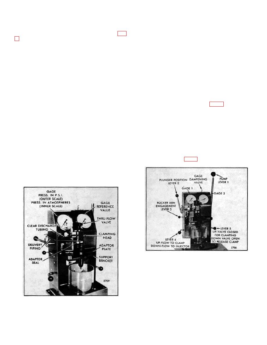
Fig. 13. Injector in Position for Testing with Tester
J 23010
Fig. 12. Injector Installed in Tester J 23010 with
clamping Head
10-3-7


