
TM 5-3895-359-14&P
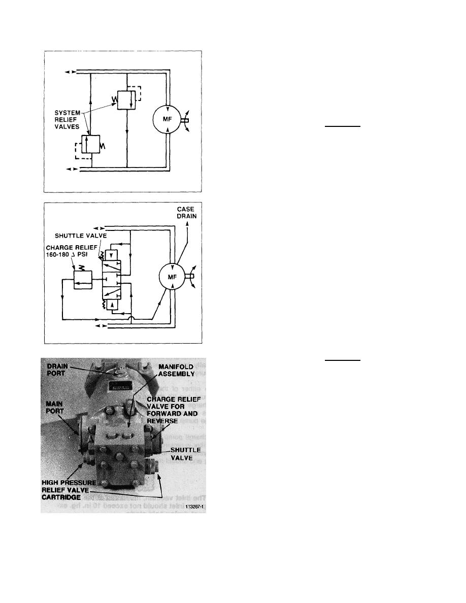
System Relief Valves
Two (2) System Relief Valves are provided for overload
protection and are located in the Manifold Assembly
mounted on the motor. These relief valves are factory
set and are of the pilot operated, cartridge type.
Changing the setting of these relief valves can be
accomplished by installing cartridges with the desired
setting. The first two (2) digits of the pressure setting
are stamped on the end of the relief valve cartridge.
CAUTION
The relief valves are factory set and
should not be tampered with except
to replace the entire cartridge.
Cooling Circuit
A Shuttle Valve and a second Charge Relief Valve are
included in the Manifold Assembly. The Shuttle Valve
provides a circuit between the low pressure hydraulic
line of the closed circuit to the second Charge Relief
Valve. This Charge Relief Valve is set at a lower
pressure (160-180 A PSI) than the relief valve located in
the Charge Pump. This Charge Relief Valve limits
Charge Pressure when the pump is in forward or reverse
(swashplate stroked out of neutral).
This system provides a means of removing hot fluid
from the main closed circuit so that cooler fluid entering
from the charge pump can be used to help reduce heat
build-up.
The Shuttle Valve is spring centered to the closed
position so that during the transition of reversing
pressures in the main hydraulic lines, no high pressure
fluid is lost from the closed circuit.
Charge Pressure
When the pump is in neutral (0 swashplate angle) the
Charge Pressure should be at 190-210 ∆PSI (above
case pressure). When the pump is in forward or reverse
(other than 0 swashplate angle) the Charge Pressure
should be at 160-180 ∆PSI (above case pressure).
CAUTION
Charge Pressure must not be less
than 160 ∆PSI for satisfactory
operation.
REMOVAL AND INSTALLATION
PUMP REPLACEMENT
1.
Remove dust shield from underside of front main
frame.
2.
Place a large oil drain pan under pump area.
3.
Remove the two universal joint U-bolts that attach
the drive line to the pump yoke.
4.
Remove and cap the pump suction line.
5.
Remove and cap the two case drive lines.
6.
Remove and cap the two high pressure hoses.
7.
Disconnect travel control cable and neutral start
switch wires from pump.
8.
Place lifting sling around the pump.
9.
Remove the pump mounting bolts and lower
pump out of mixer frame.
6-8
