TM 5-3895-359-14&P
HYDRAULIC SUPPORT SYSTEM
The Sundstrand hydrostatic transmission is easy to
install, requiring no adjustments and few auxiliary
components. It has its own hydraulic support system
which is discussed in this section.
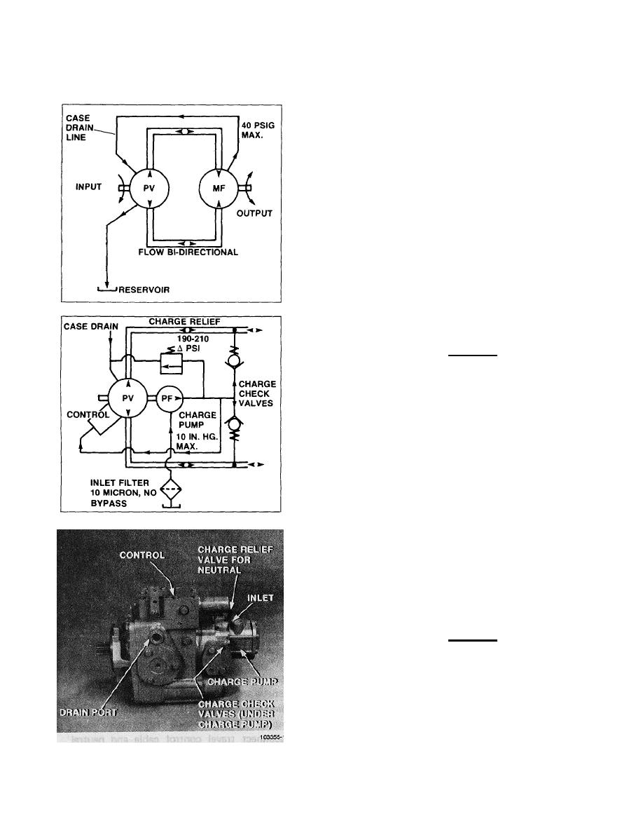
Basic Closed Circuit
The main ports of the pump are connected by hydraulic
lines to the main ports of the motor. Fluid flows, in
either direction, from the pump to the motor then back to
the pump in this closed circuit. Either of the hydraulic
lines can be under high pressure. The position of the
swashplate determines which line is high pressure as
well as the direction of fluid flow.
Case Drain
The pump and motor require case drain lines to remove
hot fluid from the system. The motor should be drained
from its topmost drain port to insure the case remains
full of fluid. The motor case drain is then connected to
the lower drain port on the pump housing and out the
upper port.
CAUTION
Case pressure should not exceed 40 PSIG.
Charge System and Inlet Filter
A fixed displacement (gear type) charge pump is
mounted on the variable displacement pump and driven
off the main pump shaft. The charge pump supplies
cool fluid to the system, keeps the system charged and
supplies fluid to operate the control system. Charge
pressure, with the pump in neutral (O flow), is limited by
a relief valve which is normally factory set for 190-210
APSI (above case pressure).
Since either of the main hydraulic lines can be high
pressure, two (2) charge check valves are used to direct
the charge supply into the low pressure line. The check
valves are contained in the pump end cap beneath the
charge pump.
The charge pump draws the fluid from the reservoir. An
inlet filter is required to insure that only clean fluid
enters the system. This filter should have a 10 micron
(nominal) rating and should not have a bypass.
CAUTION
The inlet vacuum, measured at the
charge pump inlet should not exceed
10 in. hg. except during cold starts.
6-7


