
TM 5-3895-359-14&P
ROTOR DRIVE AXLE
A. If original identification marks are not clear, mark
differential case halves with a punch or chisel (as
GENERAL
shown in photograph above) before disassembling,
for correct alignment when reassembling.
The Rockwell-Standard Company Unit-Type Housing
B. Cut lock wire, remove bolts or cap screws and
Drive Unit is a single-reduction drive of hypoid design.
separate case halves.
The differential and gear assembly is mounted on
C. Remove spider, pinions, side gears and thrust
tapered roller bearings with the cups assembled in the
washers.
case and cover halves of the housing. The straddle
D. Remove rivets and separate gear and case if
mounted pinion has two tapered roller bearings located
required.
forward of the pinion teeth and a radial bearing at the
inner end.
REMOVE GEAR RIVETS
The pinion shaft is splined to accommodate the flange
and the bearing pre-load controlled by hardened and
ground spacers of the correct thickness between the
bearings. Bearings are retained in position by the
companion flange nut.
DISASSEMBLE AXLE
A. Before disassembling, place length of pipe or
suitable support, slightly smaller than axle shaft
splines, approximately two-thirds through axle from
the case side to prevent dropping the differential
assembly.
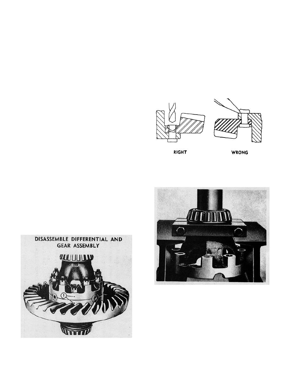
1. Carefully centerpunch rivets in center of head.
2. Use drill 1/32" smaller than body of rivet to drill
B.
Remove bolts, nuts and washers from case and
through head.
cover and remove cover half.
3. Press out rivets.
C. Remove differential and gear assembly.
D. Remove pipe.
DISASSEMBLE DRIVE UNIT
DISASSEMBLE DIFFERENTIAL AND GEAR
ASSEMBLY
E. Remove differential bearings with bearing puller if
necessary to replace.
REMOVE PINION AND CAGE ASSEMBLY
The differential and gear assembly must be
removed before the pinion and cage assembly can be
disassembled.
4-12
