TM 5-3895-342-34
1.
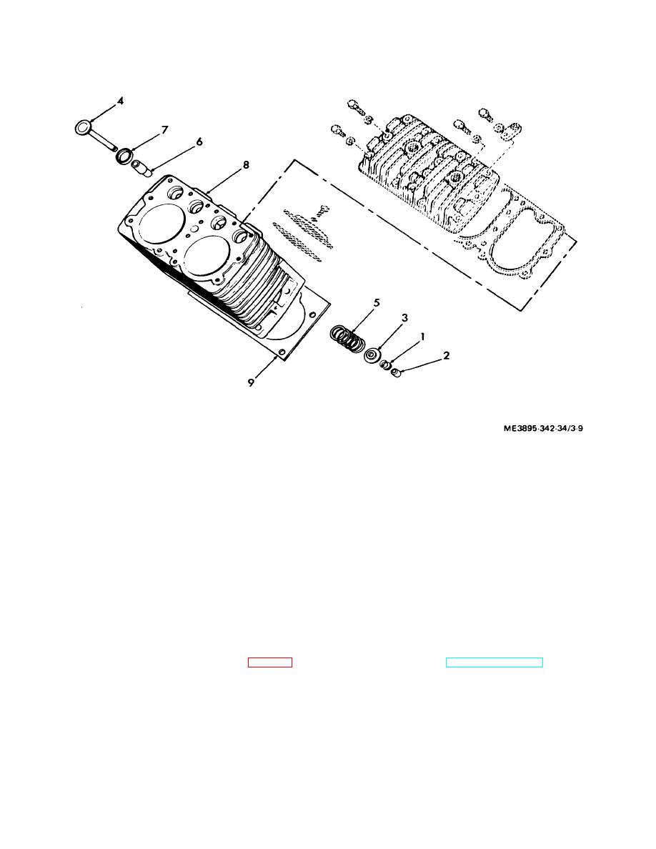
Valve Spring Seat Retainer
5.
Spring
2.
Valve Rotor Cap
6.
Valve Guide
3.
Valve Spring Seat
7.
Valve Seat Insert
4.
Valve
8.
Cylinder Block
Figure 3-9. Valve assembly, valve inset and valve guide, exploded view.
Note.
Tag each part and keep
assemblies
tool. Install a new valve seat insert by shrinking the insert
with dry ice. Repair or replace excessively worn or
separated for accurate reinstallation.
damaged parts.
c. Installation. Install the valve assemblies, valve
b.
Cleaning, Inspection and Repair.
inserts, and guides in reverse of the instructions in
(1) Clean all parts with cleaning solvent.
subparagraph a above.
(2) Inspect all parts for wear and damage.
Note. Measure each valve stem diameter and the
3-12. Gear Cover
a. Removal
clearance between the valve stem and the valve stem
guide. Reface the valve face to the proper angle and
(1) Remove governor, magneto, and flywheel
grind the mating on the valve at insert. See table 1-1 for
and flywheel shroud (TM 5-3895-342-12).
the proper tolerances and fit for all parts.
(2) Drain oil from engine (refer to current
Note. Remove valve seat insert with a suitable
lubrication order).
3-15


