TM 5-3895-369-14
VOLTAGE TEST
(1) Remove additive instrument panel
(pare 4-155).
(2) Power up STE/ICE-R to engine battery
(TM 9-4910-571-12&P, in TK mode).
(3) Start engine (pare 2-9).
(4) Follow Additive System Operating
Procedures (para 2-12[a]) steps 3-6.
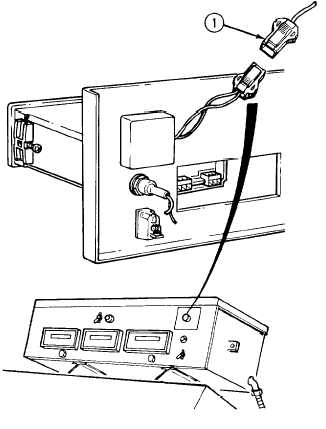
(5)
Perform voltage test # 89 at input side
(1) of speed pump control.
(a) If 12 to 14 Vdc are present at
input (1), replace pump speed
control (para 4-155).
(b) if 12 to 14 Vdc are not present at
input (1), indicates faulty flow
control power switch.
VOLTAGE TEST
(1) Remove additive instrument panel
(para 4-155).
(2) Power up STE/ICE-R to engine battery
(TM 9-4910-571-12&P, in TK mode).
(3) Start engine (para 2-9).
(4) Follow Additive System Operating
Procedures (pare 2-12[a]) steps 3-6.
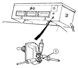
(5) Perform voltage test # 89 at input
side (1) of flow control power switch.
(a)
If 12 to 14 Vdc are present,
replace flow control power switch
(pare 4-l 55).
(b) If 12 to 14 Vdc are not present,
indicates faulty hydraulic pressure
switch.
4-123