TM 5-3895-369-14
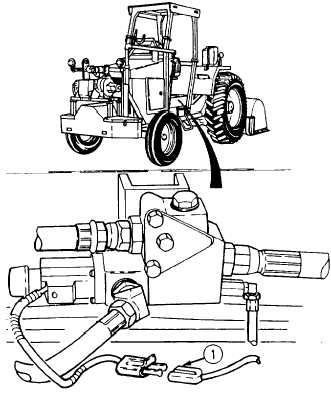
SOLENOID VOLTAGE TEST
(1) Remove forward floor plate
(para 4-132).
(2) Power up STE/ICE-R to engine battery
(TM 9-4910-571-12&P, in TK mode).
(3) Start engine (para 2-9).
(4) Follow Additive System Operating
Procedures (pare 2-12[a]) steps 3-6.
(5) Perform voltage test # 89 at input side
(1) of flow control valve solenoid.
(a) If 12 to 14 Vdc is present at
input side of solenoid, perform
continuity test.
(b) lf 12 to 14 Vdc is not present at
input side of solenoid, go to
step # 4.
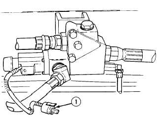
SOLENOID CONTINUITY TEST
(1) Remove forward floor plate
(para 4-132).
(2) Power up STE/ICE-R to engine battery
(TM 9-4910-571-12&P, in TK mode).
(3) Perform continuity test # 91 across
flow control valve solenoid wire
connector (1).
(a) If continuity test is 0, replace
flow control valve (para 4-138).
(b) If continuity is greater than 0,
indicates faulty pressure sensor.
4-121