
TM 5-3895-369-14
5-90. ROTOR DRIVE ASSEMBLY REPAIR (CONT).
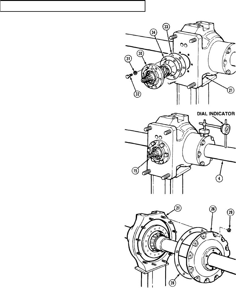
(24) Install shims (33), with the thickness equal
to the measurement recorded during
disassembly, plus an additional shim (34)
of .003 in. thickness to bearing cage
assembly (30).
(25) Install bearing cage assembly (30) in gear
housing (21) with six lockwashers (31) and
screws (32). Tighten screws 125 lb-ft
(170 Nm).
(26) Rotate pinion shaft (15) several times to
obtain correct pattern in dye on ring gear.
(27) Using a dial indicator, measure and record
ring and pinion backlash in four equally
spaced positions around axle (4).
(28) If backlash is within 0.006 - 0.012 in.
(0.152 - 0.305 mm), go to step (42).
If backlash is not within these limits,
continue to step (29).
(29) Remove nuts (29), gear cover (26), and
gasket (28) from gear housing (21).
5-543