• Home
  • Download PDF
  • Order CD-ROM
  • Order in Print
ROTOR DRIVE ASSEMBLY REPAIR - Continued

Maintenance Manual For Mixer, Rotary Tiller Page Navigation
  1204    1205    1206    1207    1208  1209  1210    1211    1212    1213    1214  
img
TM 5-3895-369-14
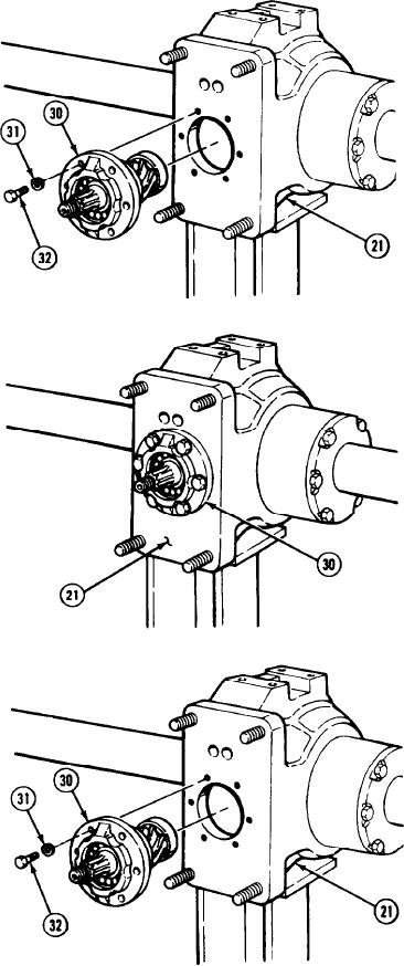
(21) Install bearing cage assembly (30) in gear
housing (21) with six lockwashers (31) and
screws (32). Tighten screws 125 lb-ft
(170 Nm).
(22) Measure and record space between bearing
cage assembly (30) and face of housing (21).
(23) Remove six screws (32), lockwashers (31),
and bearing cage assembly (30) from gear
housing (21).
5-642


Privacy Statement
Press Release
Contact

© Copyright Integrated Publishing, Inc.. All Rights Reserved.