
TM 5-3895-369-14
(11)
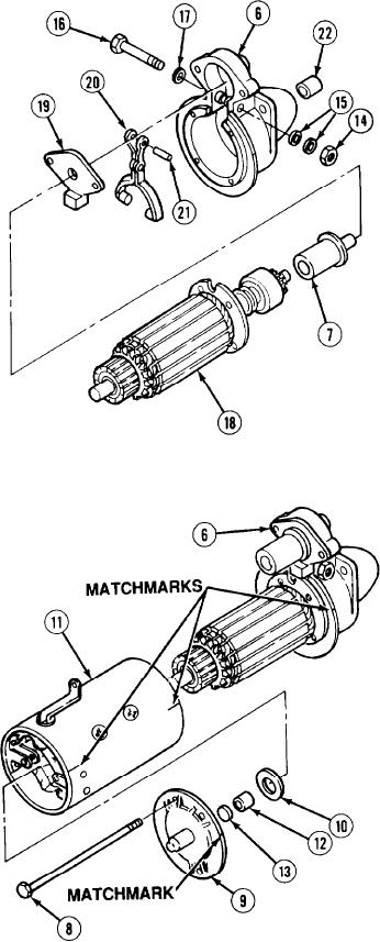
If removed, install bushing (22) in drive
housing (6).
(12)
Install lever (20) and rubber boot (19) on
plunger (7) with pin (21).
(13)
Position lever (20) on armature (18) and
install in housing (6) with screw (16), three
special washers (17 and 15), and
locknut (14).
(14)
Fully seat rubber boot (19) in drive
housing (6).
(15)
If removed, install wick (13) and
bushing (12) in end cap (9).
(16)
Align matchmarks and install coil
housing (11) washer (10) and end cap (9) on
drive housing (6) with two screws (8).
5-303