
TM 5-3895-369-14
Do not apply grease on outer diameter of
bearing halves or damage may result to
bearing halves, related bearing caps, and
crankshaft.
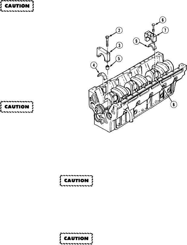
(10) Lubricate six top rod bearing halves (9) and
seven top bearing halves (4) on convex side
only with general purpose grease.
(11) Install six top rod bearing halves (9) in six
rod caps (7).
(12) Lubricate threads of 12 screws (6) and
underside of six rod caps (7) with engine oil.
Rod bearing caps and connecting rods have
numbers located on one side. Numbers
must be alined and match. Failure to do so
will result in damage to crankshaft and
connecting rod assemblies.
(13) Install six rod caps (7) on six connecting rods (8) with 12 screws (6). Do not tighten screws.
(14) If removed, install 14 ring dowels (5) in seven bearing caps (3).
Do not apply grease on outer diameter of bearing halves or damage may result to bearing halves, related
bearing caps, and crankshaft.
(15) Lubricate seven top bearing halves (4) with general purpose grease.
(16) Lubricate 14 screws (2) and seven bearing caps (3) with engine oil.
Bearing caps have numbers located on top near ring dowels. Numbers must face oil cooler side of engine
beginning with number 1 at front of engine (fan side). Failure to properly install could cause damage to
engine.
(17) Install seven bearing caps (3) with 14 screws (2).
5-143