
TM 5-3895-369-14
5-13. CYLINDER HEAD ASSEMBLY REPAIR (CONT).
(15) Check valve stem tip for flatness. Resurface
CYLINDER
tip if required.
VALVE
BLOCK
(16) Install each valve in cylinder block matching
marks made in disassembly.
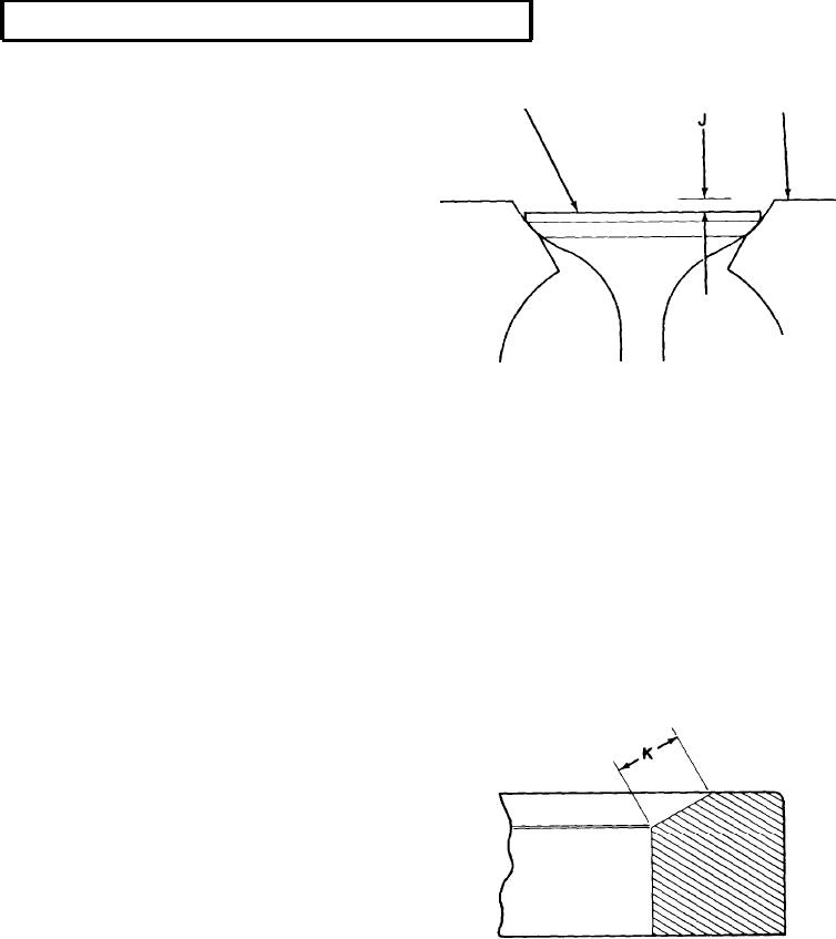
(17) Measure and record valve depth at position
J. Normal measurement is between 0.039 to
0.060 in. (0.99 - 1.52 mm). If measurement is
below normal, grind valve seat. If
measurement is above normal, replace valve.
(18) Check valve seats in cylinder head for burns,
scratches and other damage. If surface is
damaged, grind valve seats.
(19) If valves were ground, repeat steps (12) and (13) to ensure consistent measurement of valve seats.
(20) If valves were ground, measure valve depth again at position J. Calculate grinding depth by subtracting
present measurement by the first measurement. Grinding depth should be no greater than 0.010 in.
(0.254 mm). If greater, replace with service valve seat.
(21) Mark cylinder head to identify ground valve seats.
(22) Install each valve in cylinder block in accordance with matching marks made in disassembly.
(23) Repeat step (18) to ensure proper valve depth.
(24) Apply lapping compound to each valve and valve seat. Wipe lapping compound from valve and valve seat
with lint-free cloth.
(25) Measure valve seat width at position K.
Normal measurement is between 0.060 to
0.080 in. (1.5 - 2 mm). If measurement is
below normal, grind valve seat as required.
If measurement is above normal, replace
valve seat with service valve seat.
5-134