
TM 5-3895-369-14
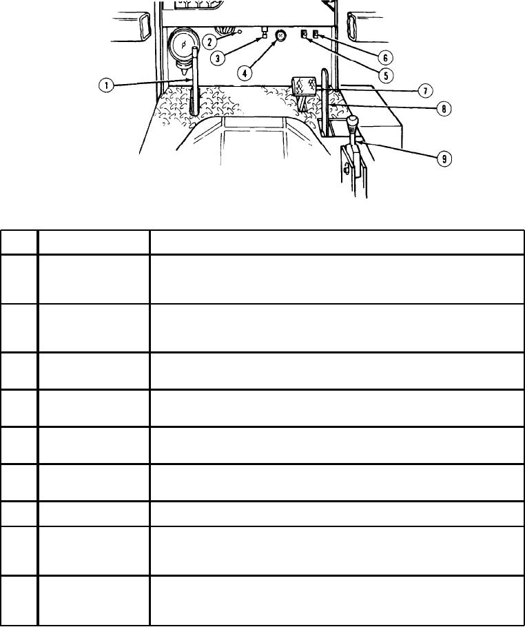
Table 2-1. Controls and Indicators.
Function
Control/Indicator
Key
Engages clutch drive rotor assembly. This lever has two positions;
Rotor Control Lever
1
ROTOR ON and ROTOR OFF. ROTOR ON engages rotor and ROTOR OFF
disengages rotor.
Activates emergency steering system. Allows steering of vehicle in the event of
Emergency Steering
2
engine failure.
Switch
Indicates restriction of air intake system. When restriction indicator button pops
Air Cleaner
3
up, air intake filter should be serviced or obstruction removed.
Restriction Indicator
Indicates restriction of hydraulic filter. When gauge reads 10 to 30 in. Hg
4
Hydraulic Fluid
(254 - 762 mm Hg), filter should be changed
Vacuum Gauge
Turns front floodlights ON and OFF.
FRONT Floodlight
5
Switch
Turns rear floodlights ON and OFF.
REAR Floodlight
6
Switch
Stops forward and reverse movement of vehicle.
Brake Pedal
7
Controls speed of vehicle. Lever has three positions: full forward (LOW)
2-Speed Lever
8
provides low gear, center position (NEUTRAL) provides neutral gear, and full
backward (HIGH) provides high gear.
Manually controls brakes. The full up (vertical) position sets brakes and
9
Parking Brake
full down (horizontal) position releases brake. Brake is released by pulling lever
up then pushing forward and down.
2-2