
TM 5-3895-359-14&P
The Idle adjusting needle (14) should be seated lightly
The Main Metering Jet (4), for high speed operation is
(clockwise), then backed out 1 1/8 turns as a
preliminary setting.
With engine warmed up and
fixed (not adjustable), as standard equipment.
running at about 1200 R.P.M., fine tune idle mixture for
smooth steady running.
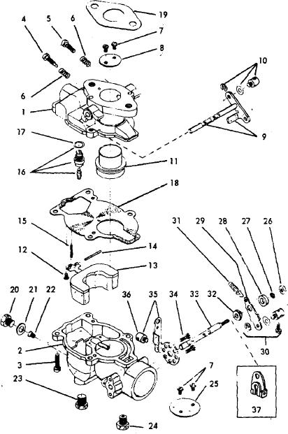
FIGURE 31. EXPLODED VIEW
Instructions and Service Parts Illustration
14-16