• Home
  • Download PDF
  • Order CD-ROM
  • Order in Print
Fig. 1 - Oil Pump Assembly.
Fig. 3 - Oil Pump Details and Relative Location of Parts.

Technical Manual For Mixer, Rotary Tiller, Soil Stabilization Diesel Engine Driven (Ded) Page Navigation
  377    378    379    380    381  382  383    384    385    386    387  
img
.
TM 5-3895-359-14&P
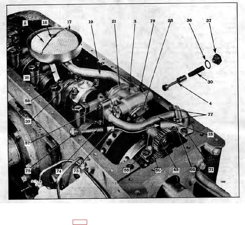
Fig. 2 - Typical Oil Pump Mounting.
An idler gear (56) is mounted on a support bracket
Pressure lubrication of the idler gear bushing is provided
which is attached to the pump body (Fig. 1).
by  means  of  a  drilled  passage  in  the  pump
10-5-5


Privacy Statement
Press Release
Contact

© Copyright Integrated Publishing, Inc.. All Rights Reserved.