TM 5-3895-359-14&P
Inspect the pressure relief valve and its seat in the
driven gear shaft must be reamed to .500" i .0005" and
pump body. If necessary, install new parts.
bushings used with the .623" diameter shaft must be
reamed to .625"* .0005".
Assemble Oil Pump
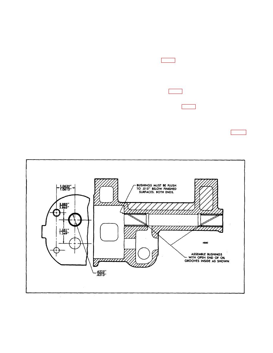
Inspect the bushings in the pump body and cover. If the
bushing are worn excessively, replace the pump body
Refer to Fig. 3, and assemble the oil pump as follows:
and cover assemblies unless suitable boring equipment
is available for finishing the new bushings. When
1. If the drive gear (23) was removed from the drive
installing new bushings, replace all of the bushings. The
shaft (13), insert the Woodruff key (14) in the keyway
bushings must be located and positioned as shown in
and apply a light coat of engine oil on the shaft. Start
Fig. 6. Also, the gear bore and the bushing bore in both
the shaft squarely into the bore of the gear and, as
the pump body and cover must be concentric within
shown in Fig. 5, press the shaft into the gear.
.001". The shaft-pump body-bushing clearance with
new parts is .0008" to .0025". The shaft-to-pump cover
The gear must be 6-15/16" from the keyway end of
bushing clearance with new parts is .0010" to .0027".
the drive shaft (Fig. 7).
In an efficient oil pump, the gears should have a free-
2. Press the dowel (88) into the pump body, if removed.
running fit (with no perceptible looseness) in the pump
housing. If the gear teeth are scored or worn, install
3. Place the idler gear support (82) in position against
new gears. The use of excessively worn gears will
the forward end of the pump body (Fig. 3) and
result in low engine oil pressure which in turn, may lead
secure the support to the body with bolt (86).
to serious damage throughout the engine.
Fig. 6 - Diameter and Location of Bushing in Oil Pump.
10-5-8


