
TM 5-3895-359-14&P
Motor Manifold
Manifold Removal
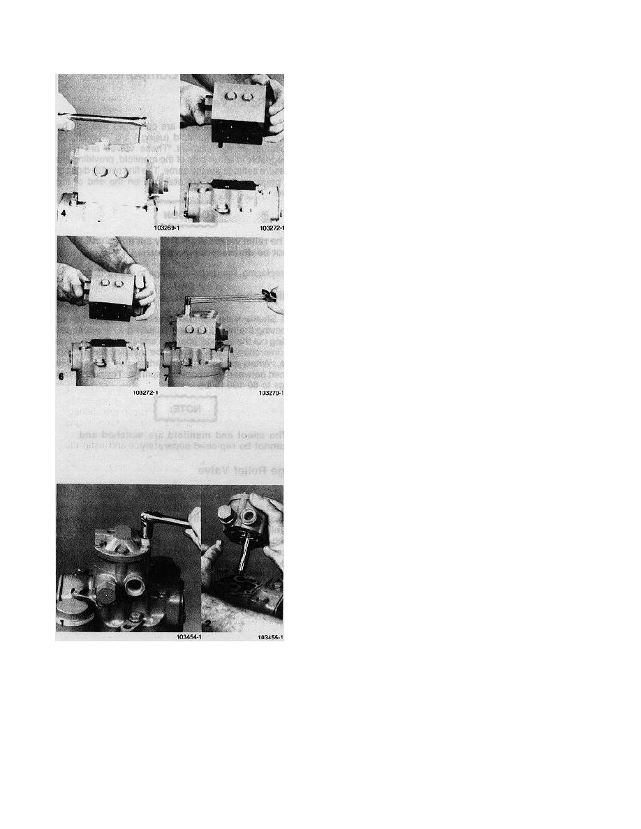
4. Remove the six (6) cap screws (use "
wrench).
5. Lift the manifold off the motor end cap. The
three (3) ports are sealed with O-rings. The
two (2) ports adjacent to each other also have
back-up rings on top of the O-rings. These
back-up rings have a rectangular cross
section and are slightly cupped where they
mate with the O-rings.
Manifold Installation
6. Place the O-ring in the port with the full
counter bore. The O-rings and back-up rings
fit in the ports with machined grooves. The O-
rings should be installed first and then the
back-up rings with the cupped side toward the
O-ring.
7. Install manifold on end cap being certain the
O-rings and back-up rings remain in place.
Torque cap screws to 16-21 ft. lbs.
Charge Pump and Charge Check Valves
Removal
1. To remove the Charge Pump, loosen the four
(4) cap screws that form a rectangular pattern.
Do not remove the screws at the top and
bottom as these hold the segments of the
pump together.
NOTE:
Protect exposed surfaces and cavities from
damage and foreign material.
2. Lift the Charge Pump off the pump end cap.
There is a spacer in the idler shaft bore that
can slip out as the pump is removed. Do not
allow it to fall into the main pump. There is a
gasket between the Charge Pump and end
cap that should be discarded.
6-20
