TM 5-3895-369-14
(15)
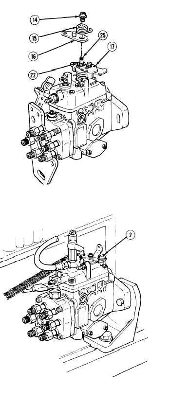
Install and align scribe marks on lower
control lever assembly (17) and control
shaft (25).
(16)
Install intermediate disc (22), upper control
lever (16), upper spring (15), and flange
nut (14). Tighten nut 60 to 86 lb-in
(7 - 10 N•m).
(17)
Repeat steps (7) and (9) to confirm correct
idling and no-load maximum speed
injection quantities.
(18)
Check pump chamber pressure at speeds
specified in calibration data with control
lever (2) in maximum position. If pressure is
within limits, go to step (19). If pressure is
not within limits, repeat step (3).
(19)
Repeat step (4) and check timer stroke at
speeds specified in calibration data with
control lever (2) in maximum position.
5-273

