TM 5-3895-369-14
4-164. ROTOR DRIVE SHAFT REPLACEMENT.
This task covers:
a. Removal
b. Installation
INITIAL SETUP
Tools
Tool kit, general mechanic’s: automotive
Wrench, torque
Materials/Parts
Lo&washers (4)
Gasket
Materials/Parts
Sealant, hydraulic (item 52, appendix E)
Equipment Condition
TM or Para
Condition Description
Para 4-176
Rotor assembly on stand.
NOTE
Rotor hood is removed for clarity.
a.
Removal.
(1)
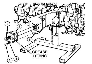
Remove four screws (1) and lockwashers (2)
from drive shaft assembly (3). Discard
lockwashers.
(2)
Remove drive shaft assembly (3) and
gasket (4) from torque tube housing (5).
Discard gasket.
b. Installation.
NOTE
Be sure grease fitting is to the right or left side only.
(1)
Install gasket (4) and drive shaft assembly (3) on torque tube housing (5).
Sealant causes immediate bonding on contact with eyes, skin, or clothing and also gives off harmful
vapors. Wear protective goggles and use in well-ventilated area. If adhesive gets in eyes, try to keep eyes
open; flush eyes with water for 15 minutes and get immediate medical attention.
(2)
Apply hydraulic thread sealant to thread of four screws (1) and install four lo&washers (2) and screws (1)
in torque tube housing (5). Tighten screws (1) 75 to 85 lb-ft (101 - 115 N•m).
(3)
Lubricate grease fitting (figure 3-1).
NOTE
END OF TASK
Follow-on Maintenance: Rotor assembly removed from stand (para 4-176).
4-530