TM 5-3895-369-14
Remove all jewelry such as rings, dog tags, bracelets, etc. lf jewelry contacts battery terminal, a
direct short may result in instant heating of tools, damage to equipment, and injury or death to
personnel.
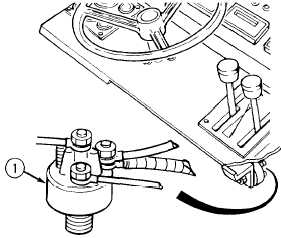
SOLENOID IGNITION SWITCH
TEST
(1) Open right engine door (para 2-14).
(2) Power up STE/ICE-R to a known good
battery source (TM 9-4910-571-1 2&P,
in TK mode).
(3) Run voltage test #67 at output side of
ignition switch (1) in ON position.
(a) if 24 ± 3 Vdc is not present,
replace ignition switch
(para 4-79).
(b) If 24 ± 3 Vdc is present,
indicates faulty ignition system
wires, connectors, or switches.
IGNITION SYSTEM
INSPECTION
(1) Remove negative battery cable
(para 4-90).
(2) Remove dash panel (para 4-126).
(3) Power up STE/ICE-R to a known good
battery source (TM 9-4910-571-12&P,
in TK mode).
(4) Run continuity test #91.
(5) Refer to electrical schematic
(Appendix H) and check ignition
system wires, connectors, and
switches.
(a) lf wires, connectors, and
switches are loose or damaged,
tighten or replace as necessary.
(b) lf wires, connectors, and
switches are ok, indicates faulty
fuel injector pump solenoid.
4-19


