TM 5-3895-359-14&P
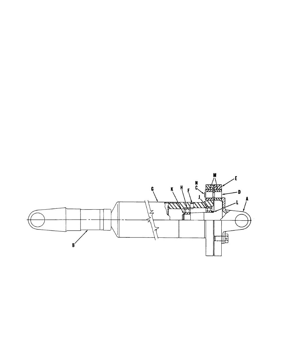
SHEAR COUPLING REPAIR (Fig. 4)
5. Clean and inspect all parts. If the shear pin (D)
Disassembly
fits loose in the coupling halves, bushings (M) need to
be replaced. Drive out bushings from the inside out. If
spring clip (C) needs replacement, remove machine
1. The coupling should be removed from the
screw and break tack weld holding clip, or remove two
driveline for bench work. Disconnect coupling from the
machine screws. Replace with new. Tack weld spring
2-speed case at flange yoke (A) and pull coupling free
clip slightly. Too much weld will remove spring temper,
from slip joint (B).
or replace the two machine screws.
2. Flip spring clip (C) back and remove shear pin
Assembly
(D). If flange (A) is removed from coupling half (E), pin
may be removed from either side, if not, pin must be
6. Slip spacer (L) on shaft of coupling half (E).
removed in direction of arrow.
Press bearing () on shaft and follow with bearing (H).
Install retainer ring(K). Slip this assembly into tube (G)
3. Back out the two set screws (F), opposite each
and tap slightly to fully seat bearings against shoulders
other in tube (G). The set screws are a "lock-in" for the
in tube. Tighten down set screws (F). Tap assembly
coupling half (E). Coupling half (E) with bearings (H)
again then back off on set screws just far enough so
and (J) may now be pulled free from tube (G), or
screws do not touch bearing. Install flange yoke (if
removed by inserting longer. same thread, screws and
removed). Yokes must be in line as shown.
use screws to jack out coupling half (E) with bearings.
7. Insert shear pin and "lock-in" with spring clip
4. Remove retainer ring (K) and bearing (H) from
(C). Reinstall coupling in driveline.
shaft of coupling half. Pull bearing (J) off shaft and
spacer (L).
Figure 4
1-4


